Complete your lab's safety training
Test runout, alignment, fixturing, speeds, feeds, materials and toolpaths for your machine
Individual Assignment
Make (design+mill+assemble) something big
Individual Assignment-
This week is for computer controlled machine and we have to design something which is cut on Wood router.So I started searching about the Design.
I see lots of funiture design Idea but I want to make something like a solution for a problem Then I realised a problem .Then finally I decided to
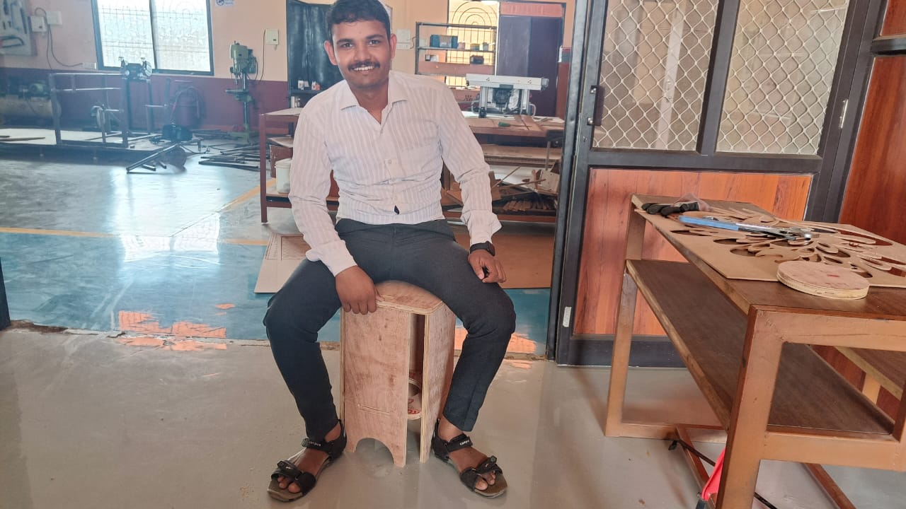
make a chair.
Types Of Material
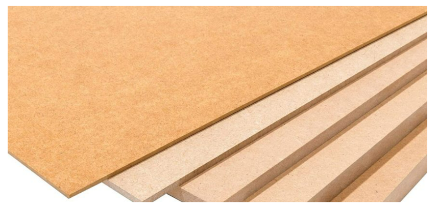
1.MDF
MDF is middle density fiberboard. It made up of soft and hard woods. Firstly this woods are crushed and converted into Fibers (fine particles) and
then some glue and additives are added. after that the mixture undergoes to high pressure and temperature and then final board is completed. MDF are
mostly used material nowdays due to its uniform surface finishing and no pour structure. It is also a cost effective product.
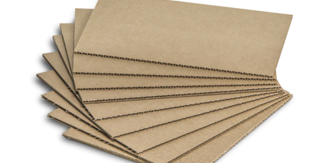
2.Cardboard
Cardboard is a one of the most used material for packaging. It is ecofriendly. Cardboard are made from plant's cellulose. CardBoard are used for packaginf
because they can resist the vibration , air flow, Sound From it. The cardboard are easily made by cellulose. cardboard contain Three layer in it . Upper and lower
layer are known as liner and made up of semicrafted paper and the middle layer known as fluting layer made up of carboard sheet.
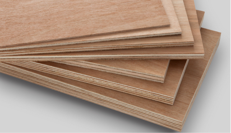
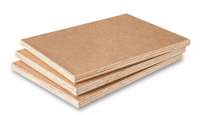
3.Plywood
Plywood is made up of wood. firstly the wood are slice into thin layers and then we combined the layers by applying glue and water reistant chemical in it.
After this Temp and pressure provided to sheet. Most of the Furniture are made by plywood because it have good workability and also have good flexibility.
It is less expensive because it is locally manufactured everywhere.
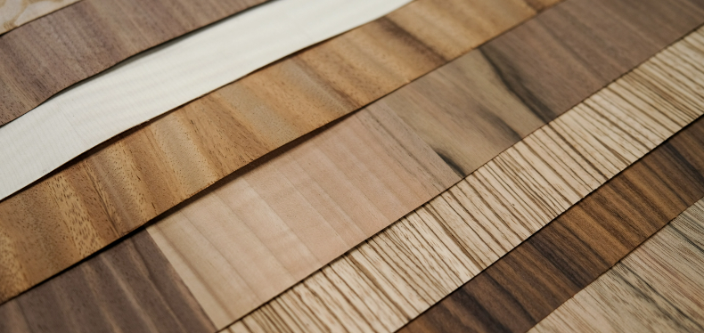
4.Vaneer
This is new material for me. When I see the picture of veneer I said it Laminates (sunmica). But when I read about It then my all doubt cleared.
vaneer is also a wooden product which is prepared in the form of slice from middle of trunk of tree. The layer or slice thickness are less Thickness.
Vaneer are used as a uper layer on the furniture for decorative purpose. The Durability of vaneer is less and required lots of maintance as compared with
laminates. Cost of this product is also high.
5.Medium Density Overlay MDO
This are similar to MDF but have high resistance to the moisture and weather resistant. This is mostly used for out sight of home like walls ,gallery
the Cost of the MDO boards are higher than the plywood.
Machine Details
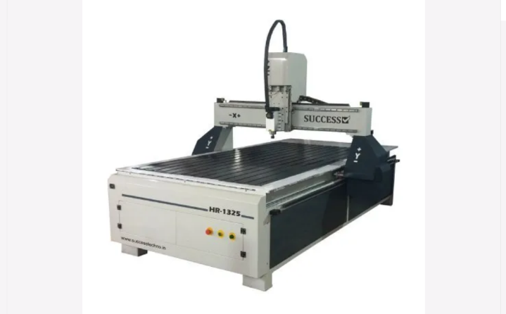
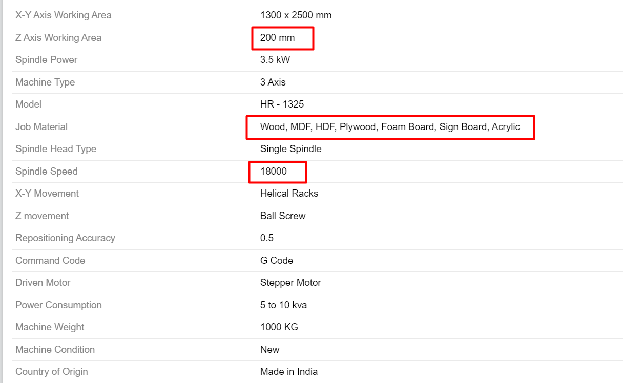
Success Techno HR1325
We have a India Manufactured CNC cutting and engraving machine. It has working area of 4*8 foot. The spindle motor of this machine cooled by air and it has
maximum RPM of 18000. It move in all three axis. It move about 200mm in Z axis. They are used in wood working like furniture and door making, wooden handicrafts etc.
The material we can or engrave on this machine are wood, Brass, Foam board, ACP sheet, Acrylic, Plywood, PVC and Plastic.
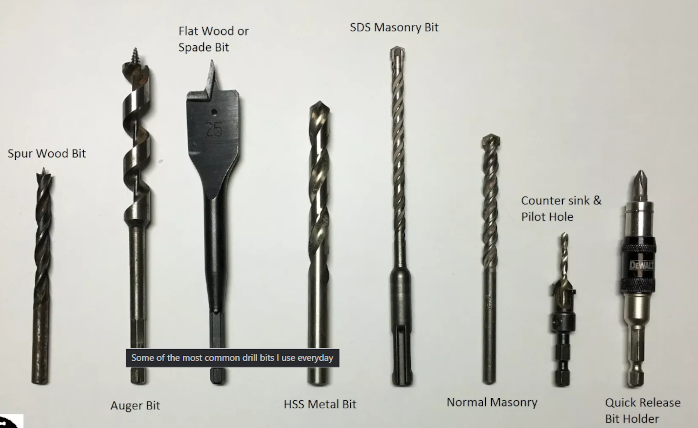
Tooling
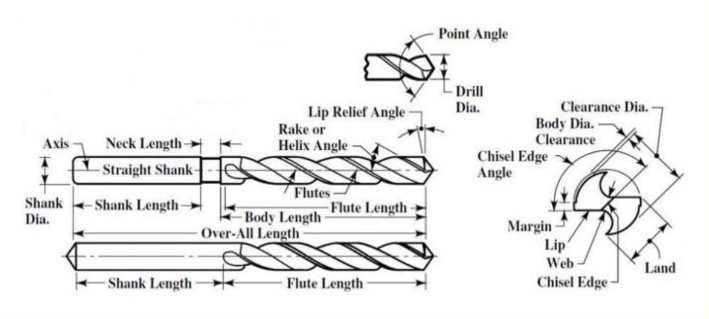
Drilling VS Milling Tool
Drilling tool
Drilling is the most commaonly operation process in everywhere. By drilling we make a hole inside a workpiece. The drilling tool works in Three stages
1.Centering Stage -Here we set the drill bit where we wanted to do hole.
2.Full drilling Stage -In this stage the drill bit go inside the material.
3.Breakthrough Stage - In this Stage drill bit passinf from the workpiece and stop.
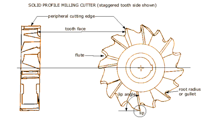
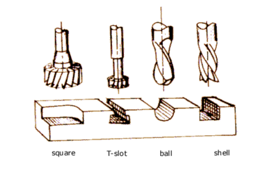
Milling Tool
Milling is the process in which we remove the uper layer of material. The tool used for milling is known as Milling tool. This tool have to move in three dimension
with rotary motion So they faces high pressure during milling. They are operated in very high speed.Mii=lling tool have flutes which remove the material from
workpiece.
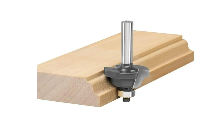
Router
Router is a tool used to make a hollow out to wood or plastic material. It also Give diffrent designing shape to the Edges of the material
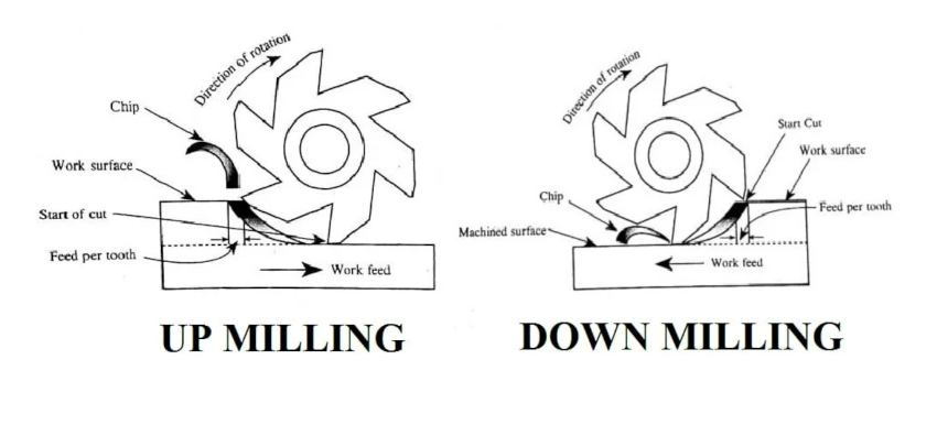
Up and Down milling
1.Up and down milling are the process of milling. In up Milling the tool rotate against the workpiece direction while in down milling the tool rotate along with
workpiece direction.
2.In up Milling the tool life are relatively less than down milling.
3.In up milling process the material are fixed with more cliping than that of down milling process
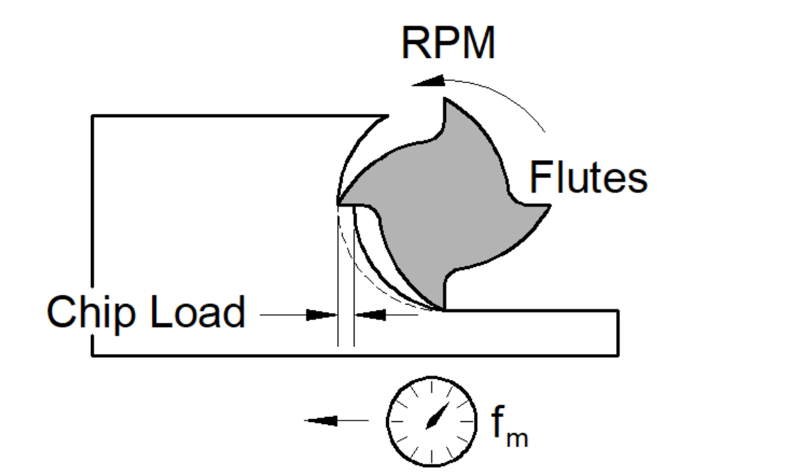
Chip Load
When a tool cut or milling the workpiece. The cutting material are removed from the workpiece in the form of chips. The thickness of this chips are playe a very
important role. The perfect chip size make tool life longer and provide a perfect finishing.
chip load is a measurment of thickness of the removing material by each eadge of tool in cut operation. It can be calculated by Following Formula-
Chip load= Feed per Minute/(No. of flutes*RPM of tool)
cutting depth - Diameter
The depth of cutting is calculated by the diameter of the tool.
cut Depth=Diameter of tool/2
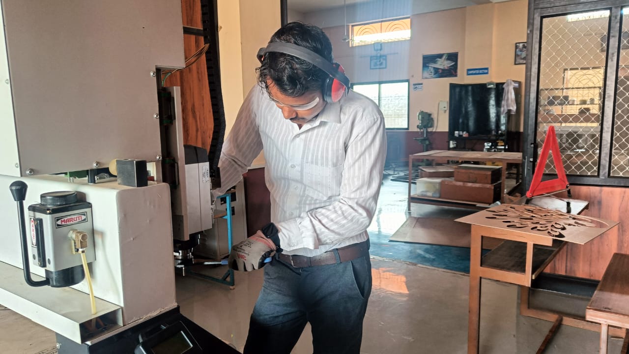
safety
1.face protection- Always use a face helmet, mask or glasses which prevent the our eyes, mouth and nose from the dust particles.
2.Ear protection and cloths- Always use ear protector while working at the machine and also wear a proper cloth. Because the machine is operated at high
speed if any part of your body part or clothes come in contact with the machine spindle it can be causes a accident.
Design
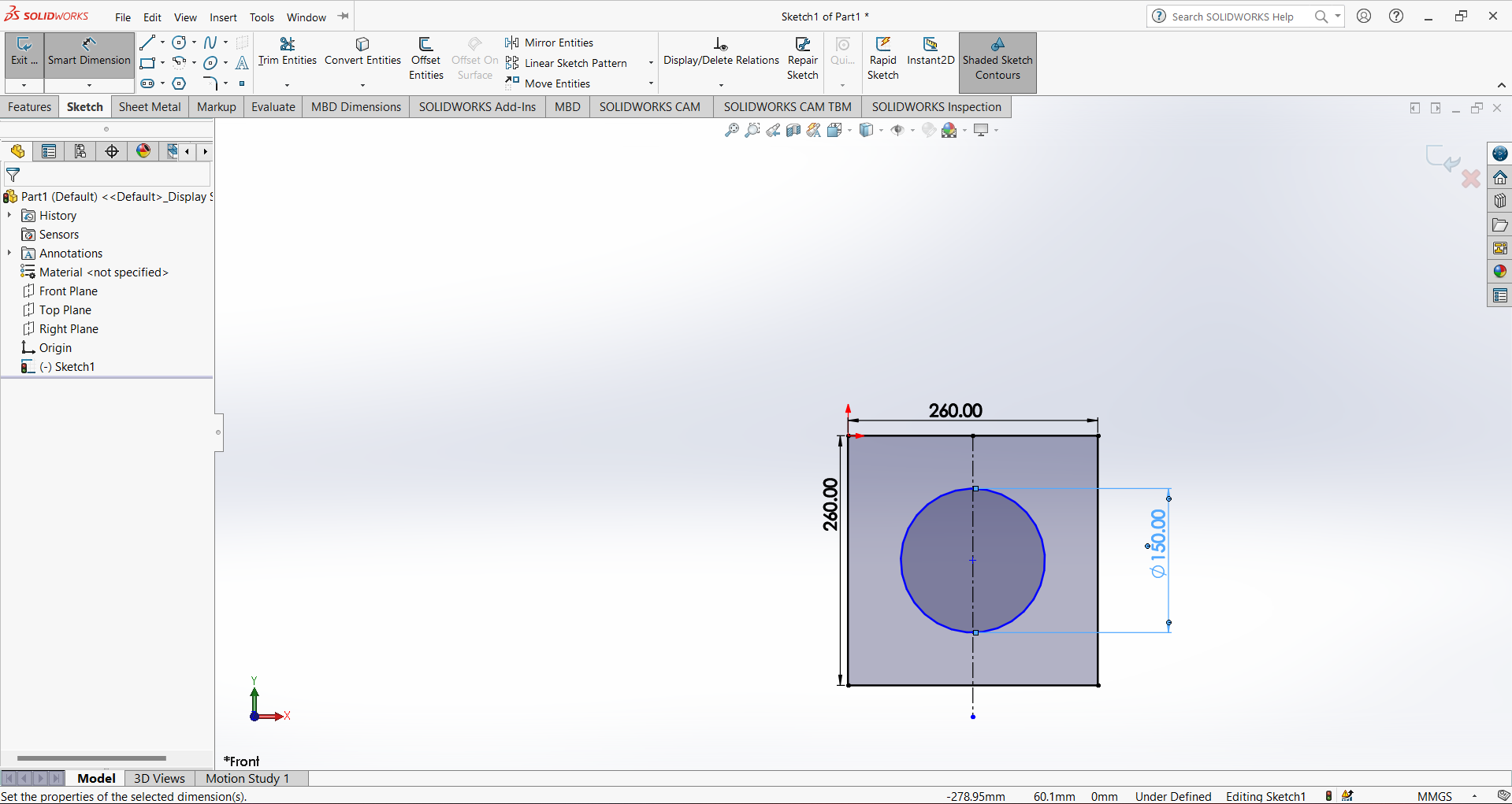
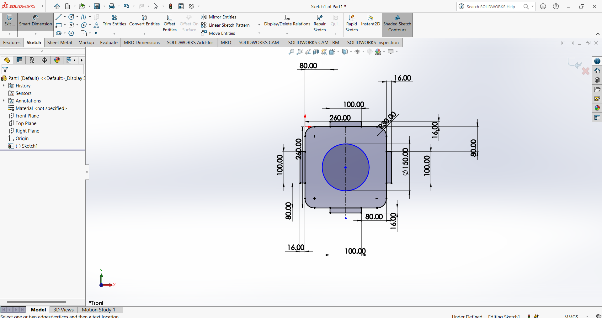
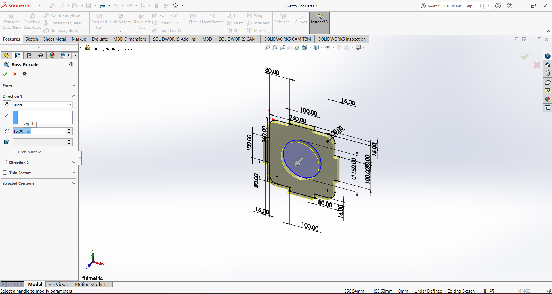
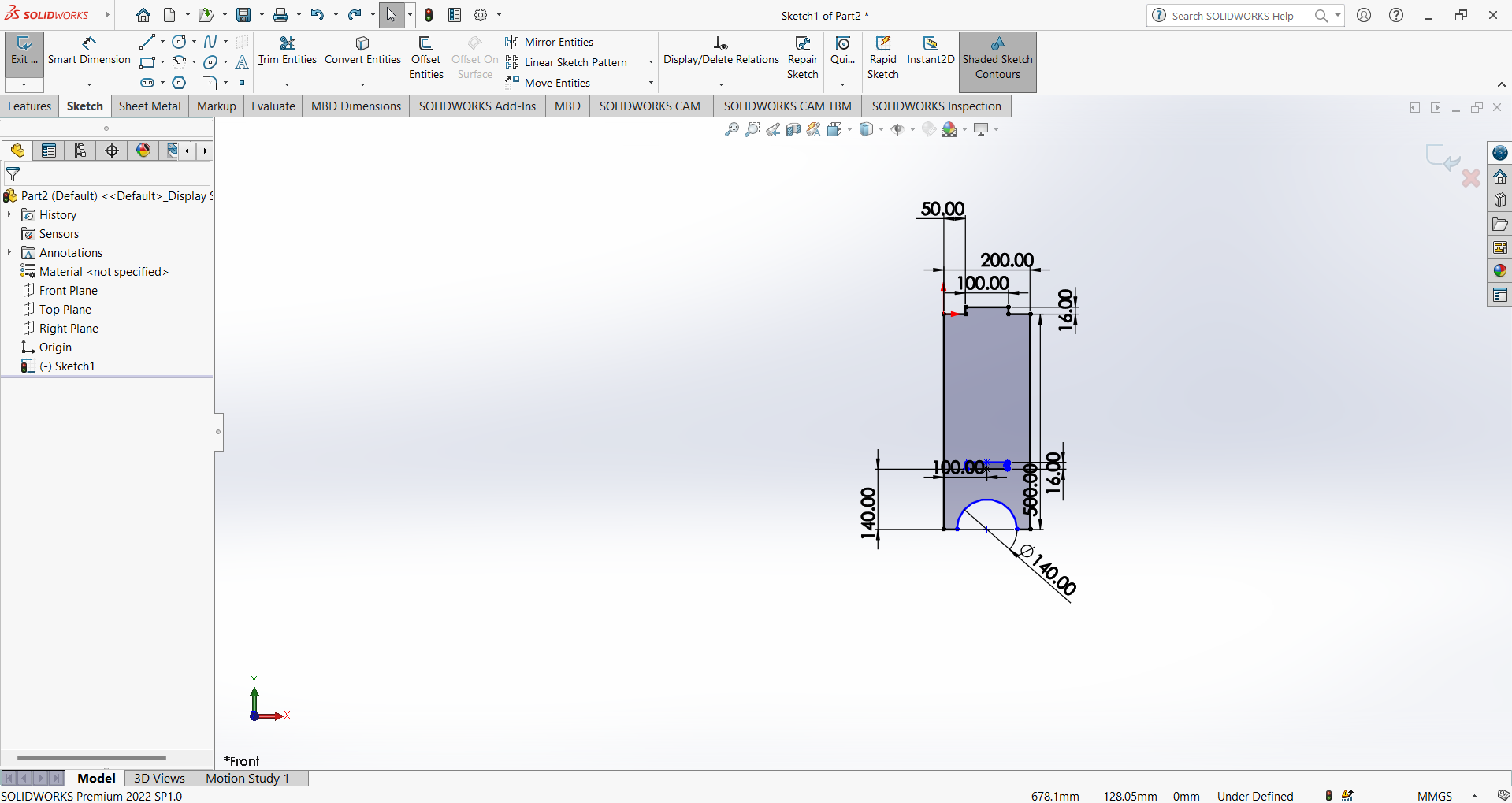
Now for the design process I selected the solidworks. And then firstly I designed the chair leg supported part.
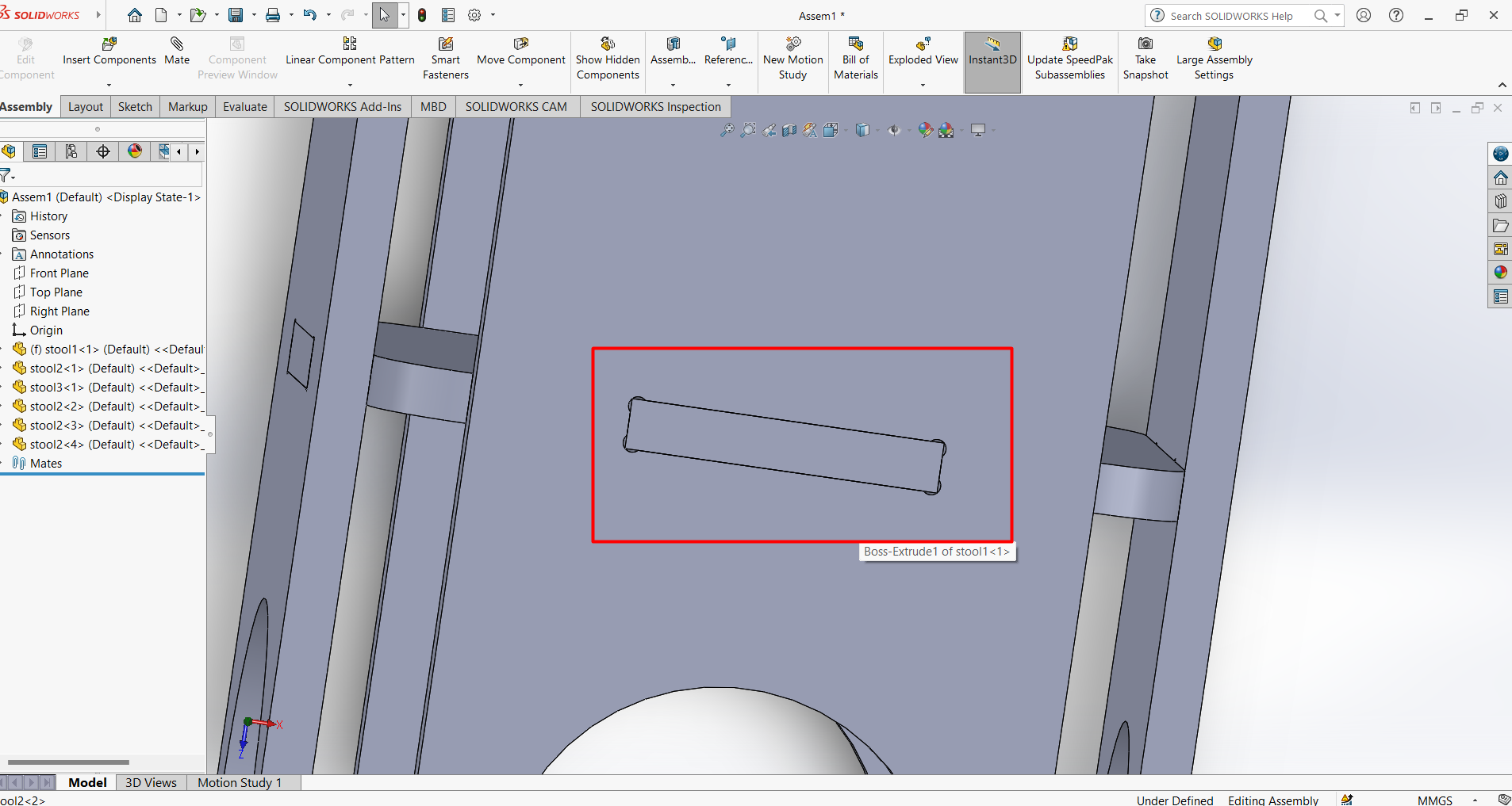
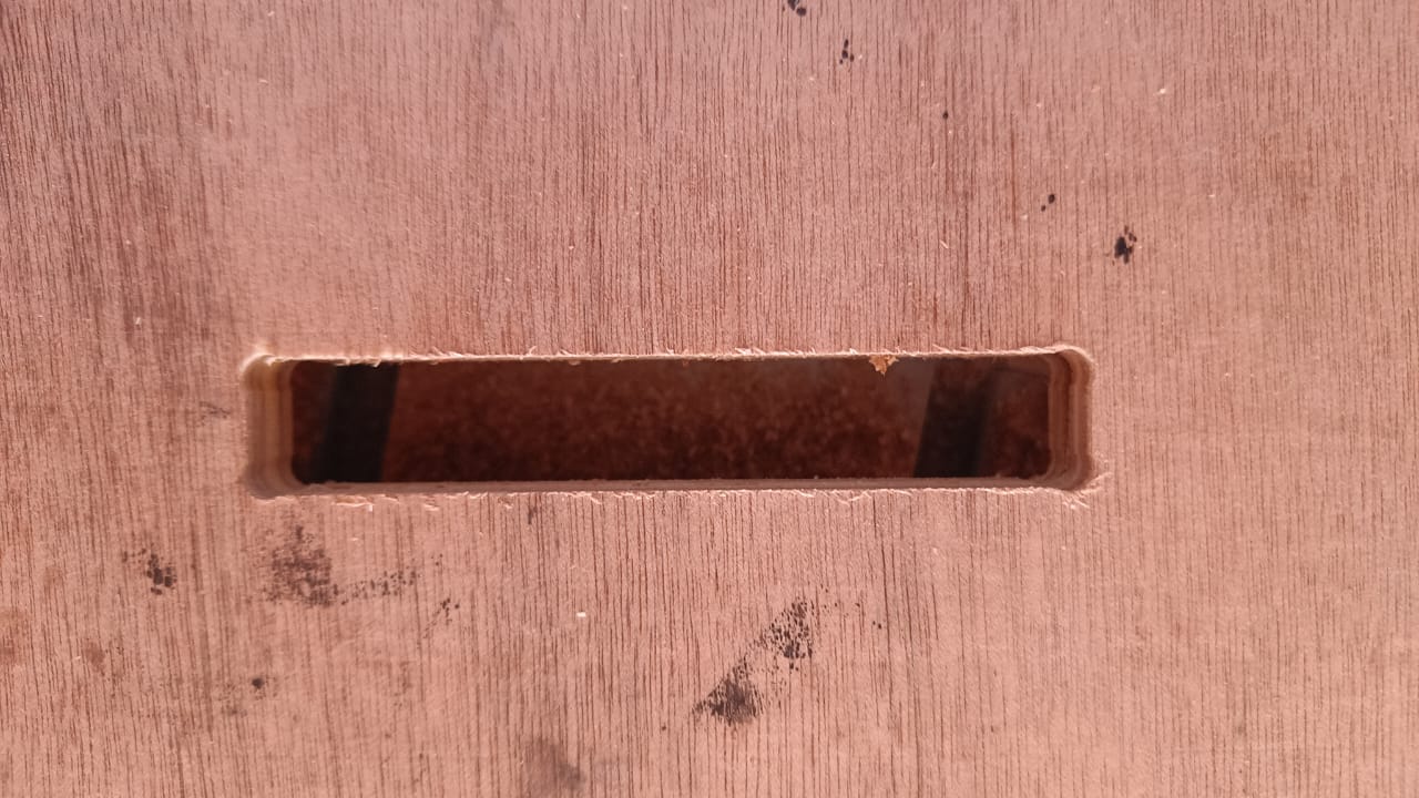
After That I design a circle inside it. Then I make part which fixed in slot. the size of the slot is 16mm*100mm. Because I am design it with 16mm plywood board.
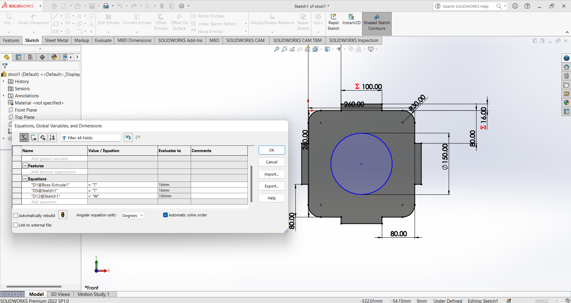
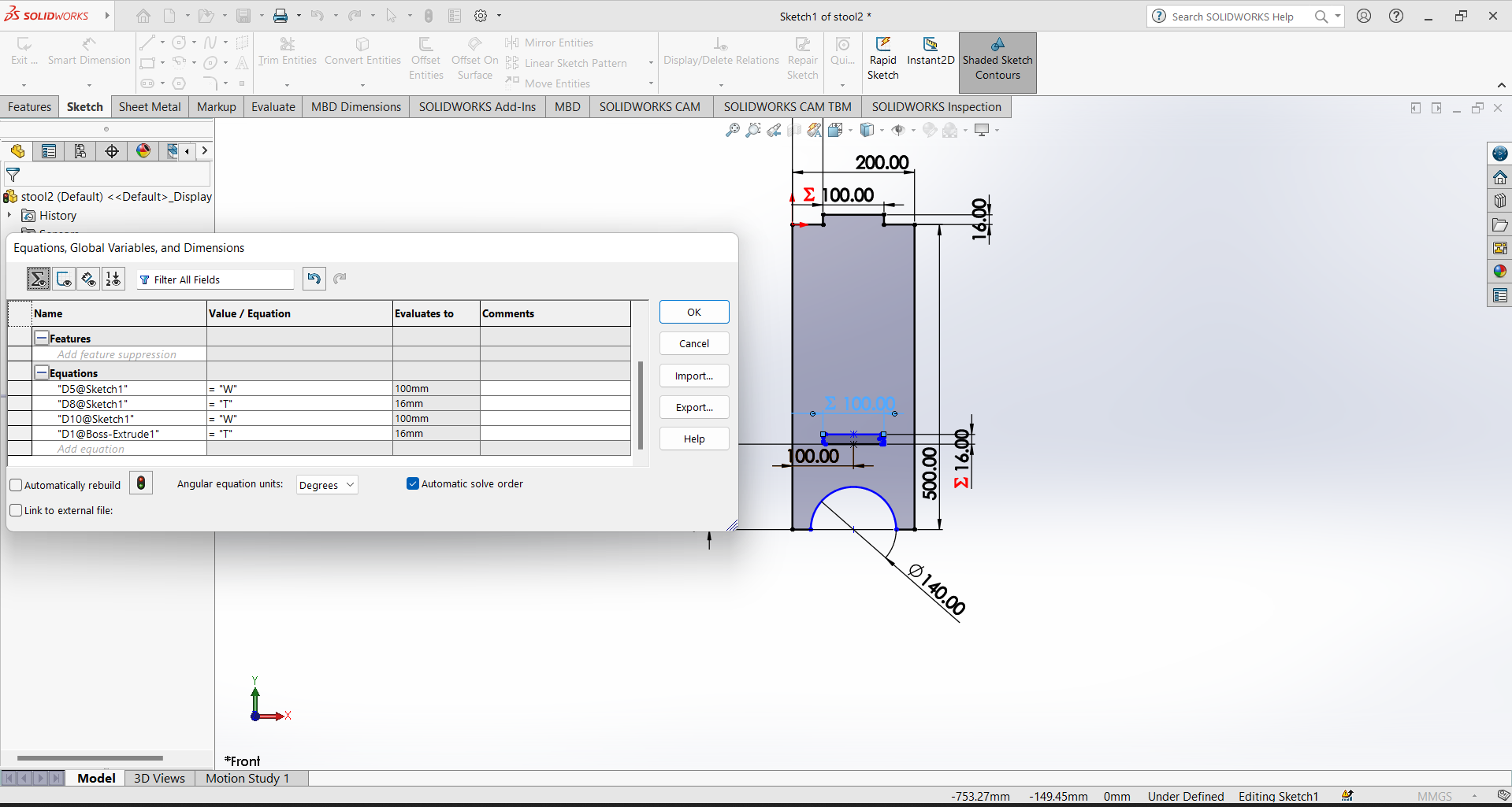
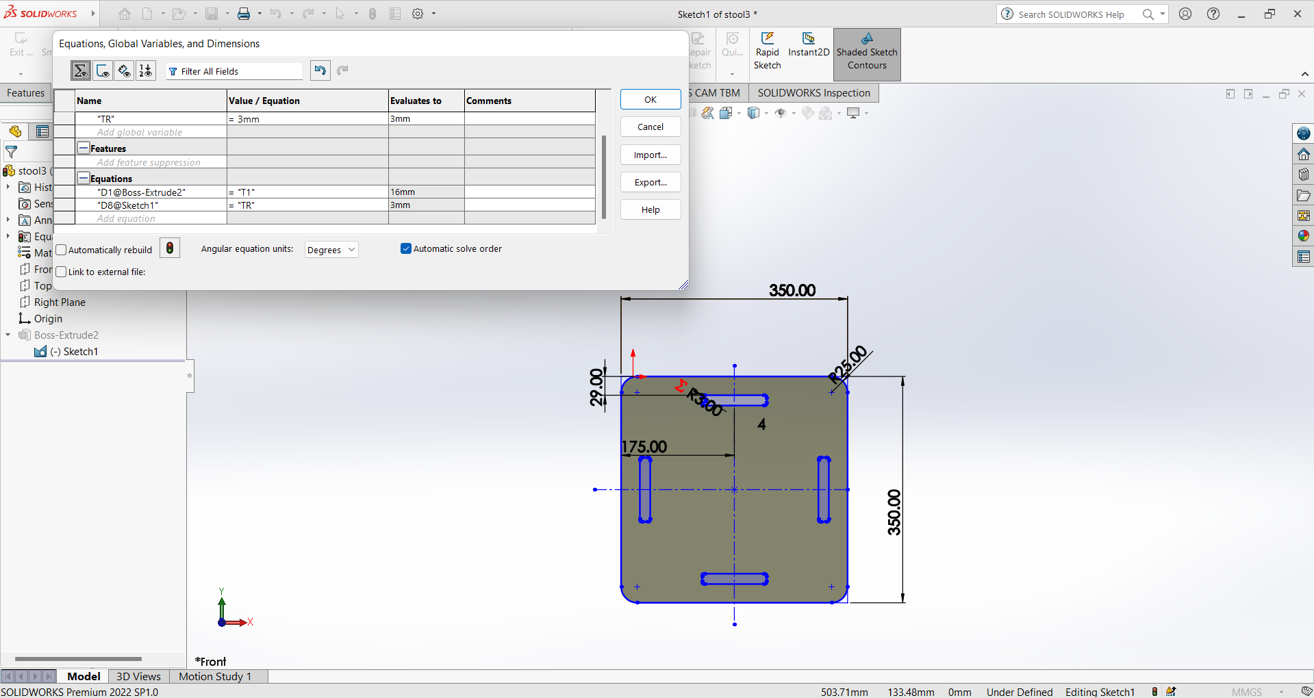
Then i also set the parametric parameter for the design. I select thickness of material and slot size as parametric. For Parametric Open he sketch give relation in the sketch entities and then go to the tool option and select equation. Then define the parametric global variable .
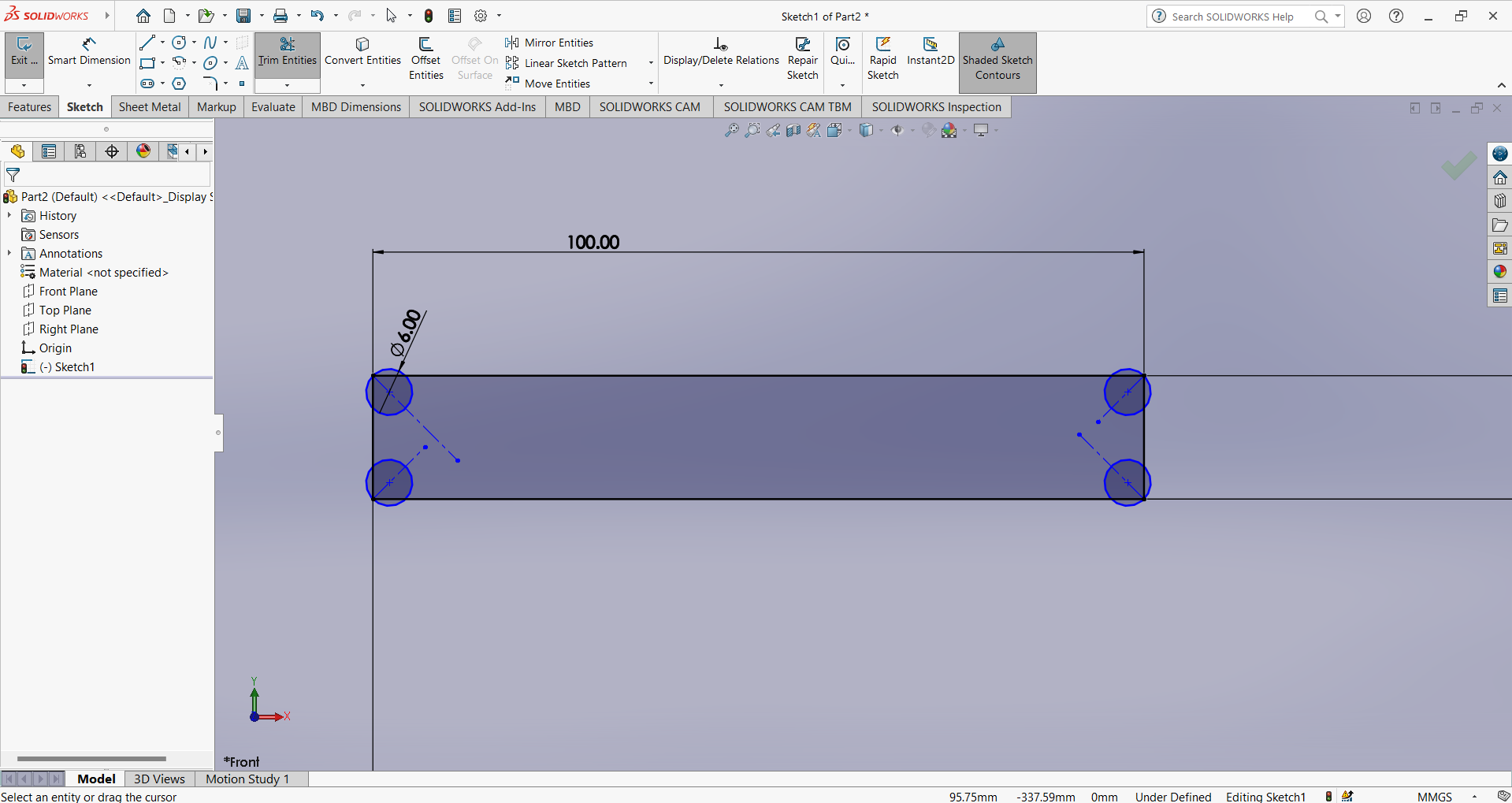
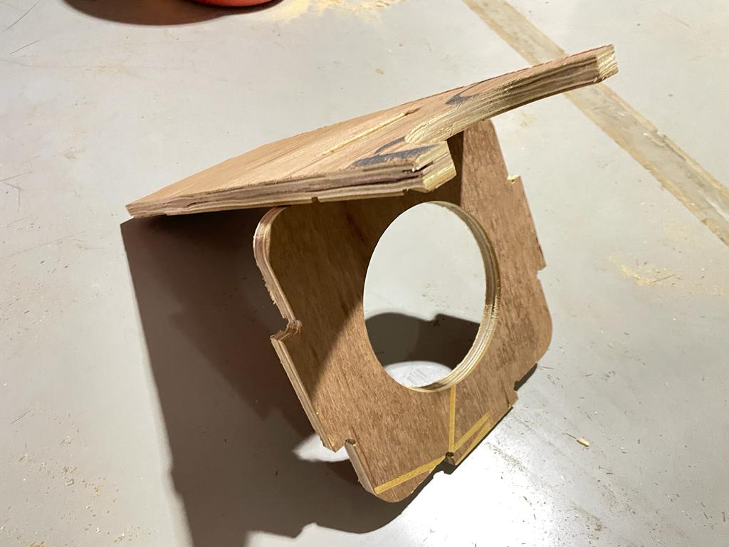
After the design of leg supported part. I design the chair leg. So I take height for this about 500mm. I also design dogbone in the slot area by which our other part perfectly fit with it.
Dogbone- Dogbone help in proper joint without gape between the material.
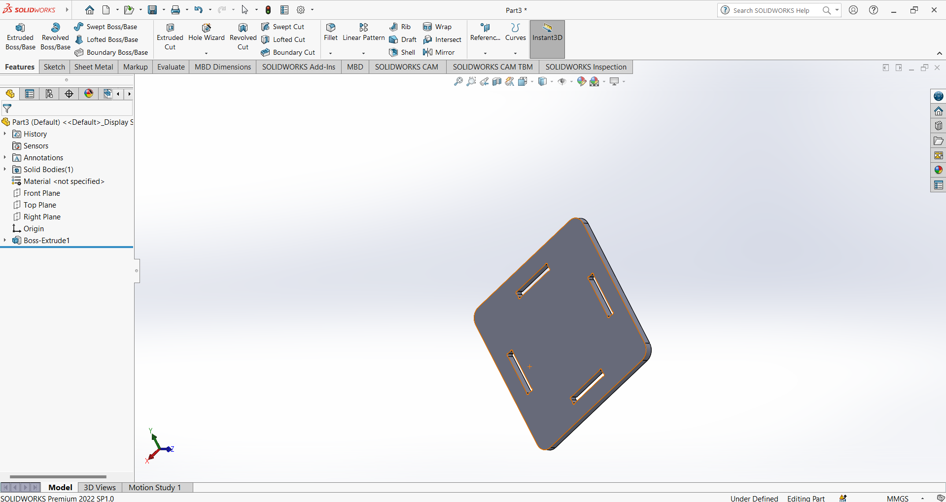
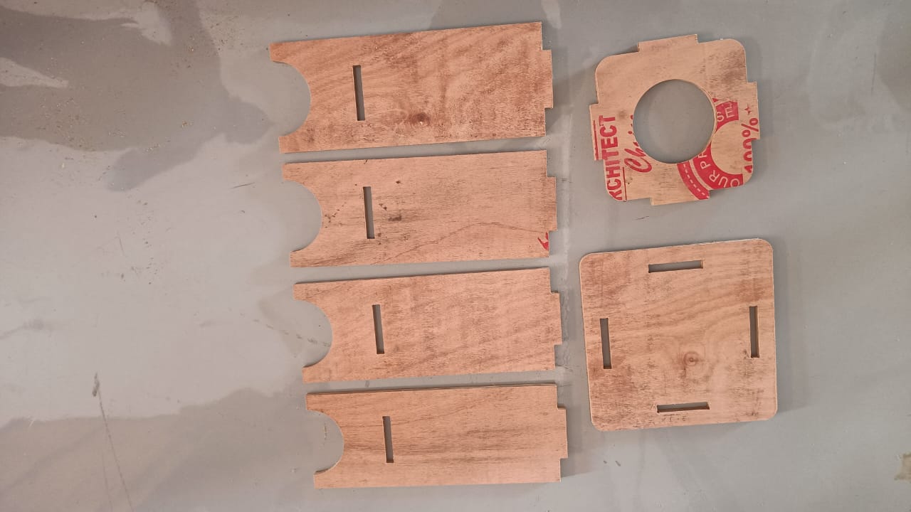
After that I design stool top. Here in the top I given four slot where the leg part of the stool get fixed with it.
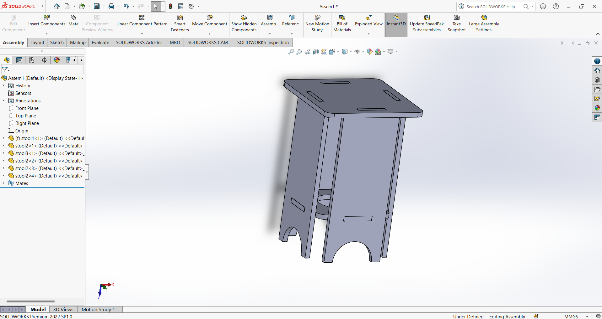
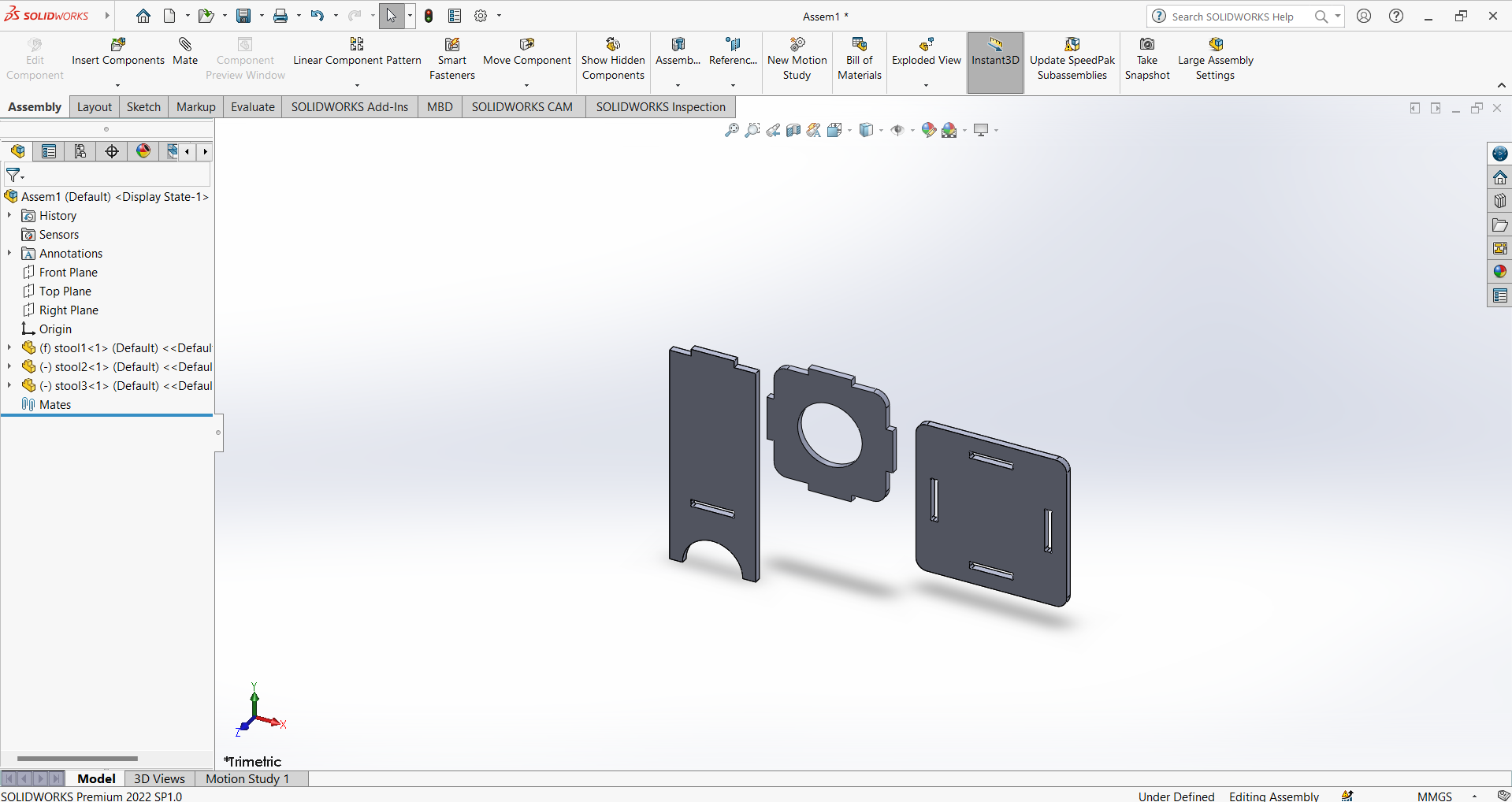
Now after design I assemble all this part in soliworks assembly. So insert this three design part in assembly.
Now I select the mate command and start the component assembly. After the assembly my final design of stool is look like that .
Toolpath Generation
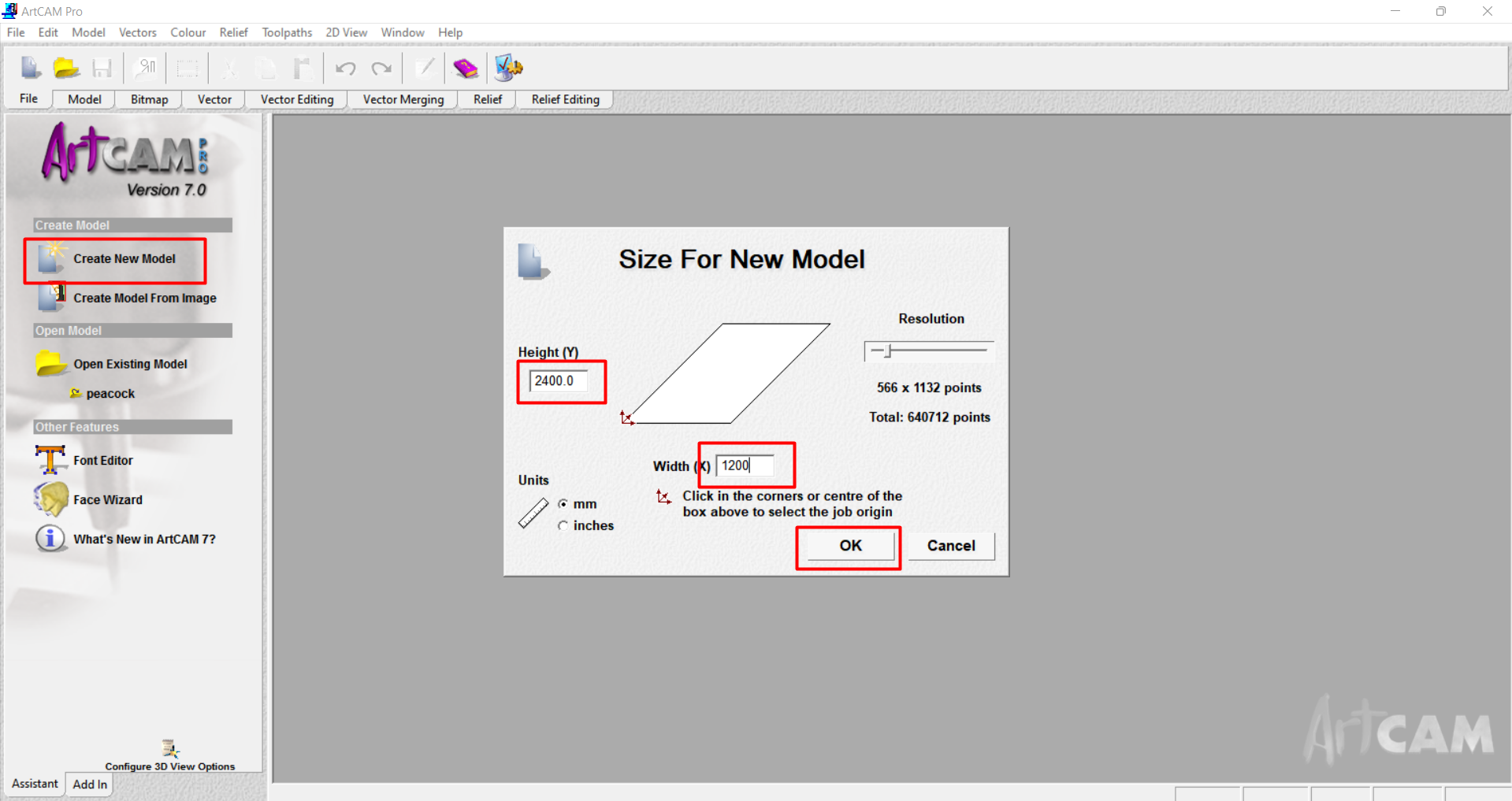
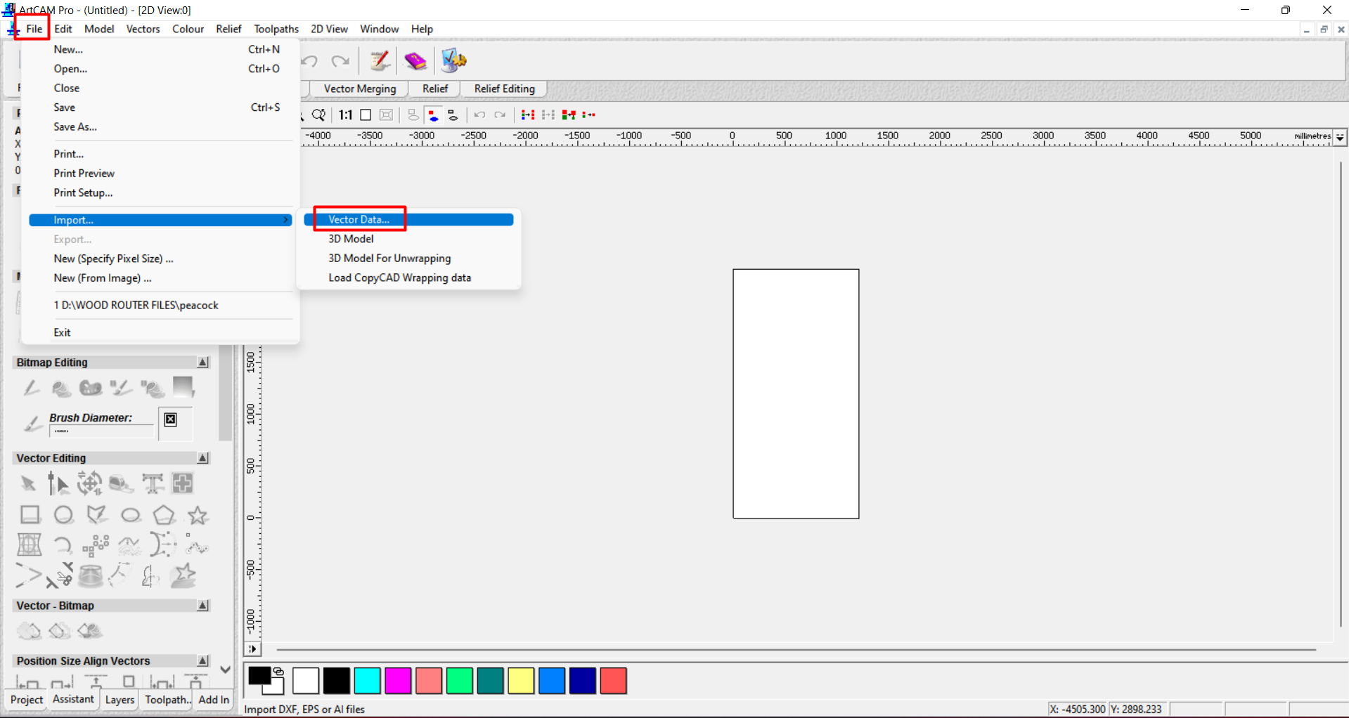
I export all the design files in Dxf formate and then I start the toolpat process. For the toolpath process I am using Artcam7 Software. After opening the software We have to select working area or workspace of thw material on which we cut our design files.
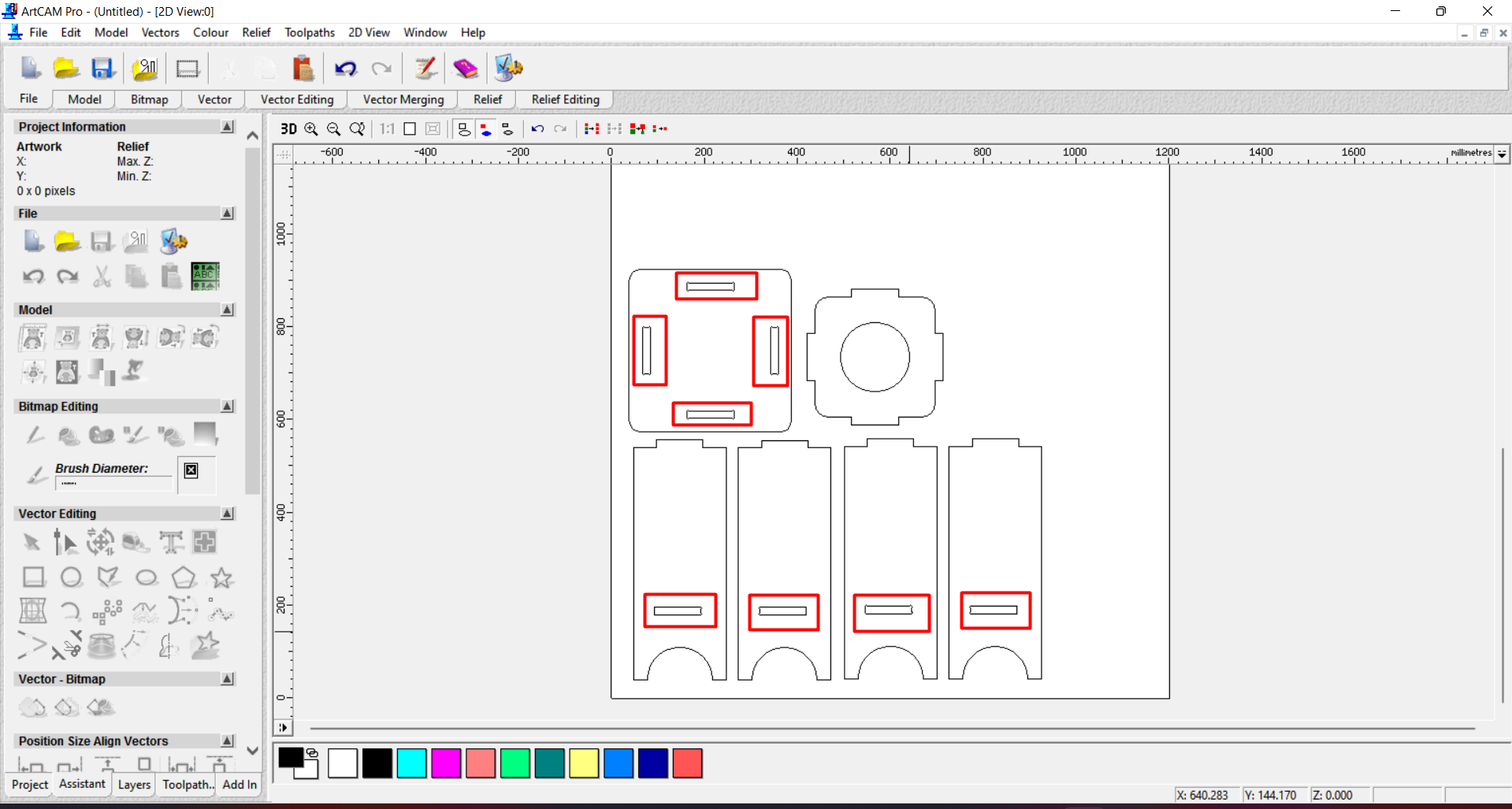
So I select the area of 2400*1200 mm. Then I import all the design files which is saved in dxf formate.
After that I arranged them properly and then I select some parts in red circle to cut from inside. and then remaining cut from outside. So I grouped inside cut part and separetly group the outside cut path.
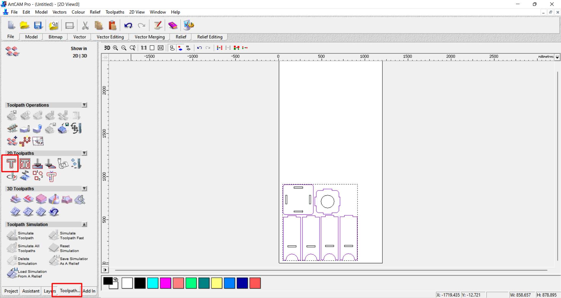
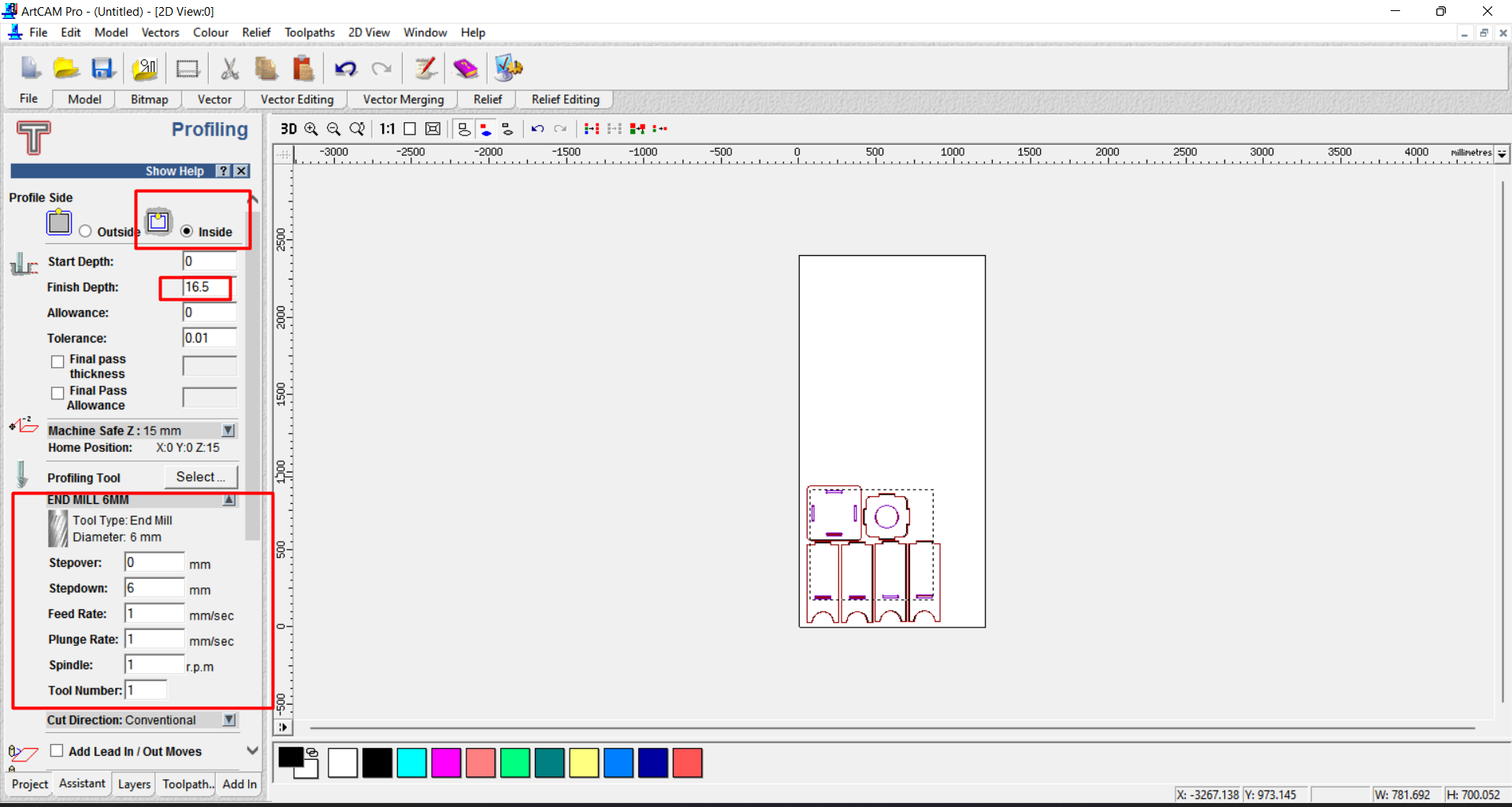
Then I Firstly selected Outside cutting and then generate the tool path for it.
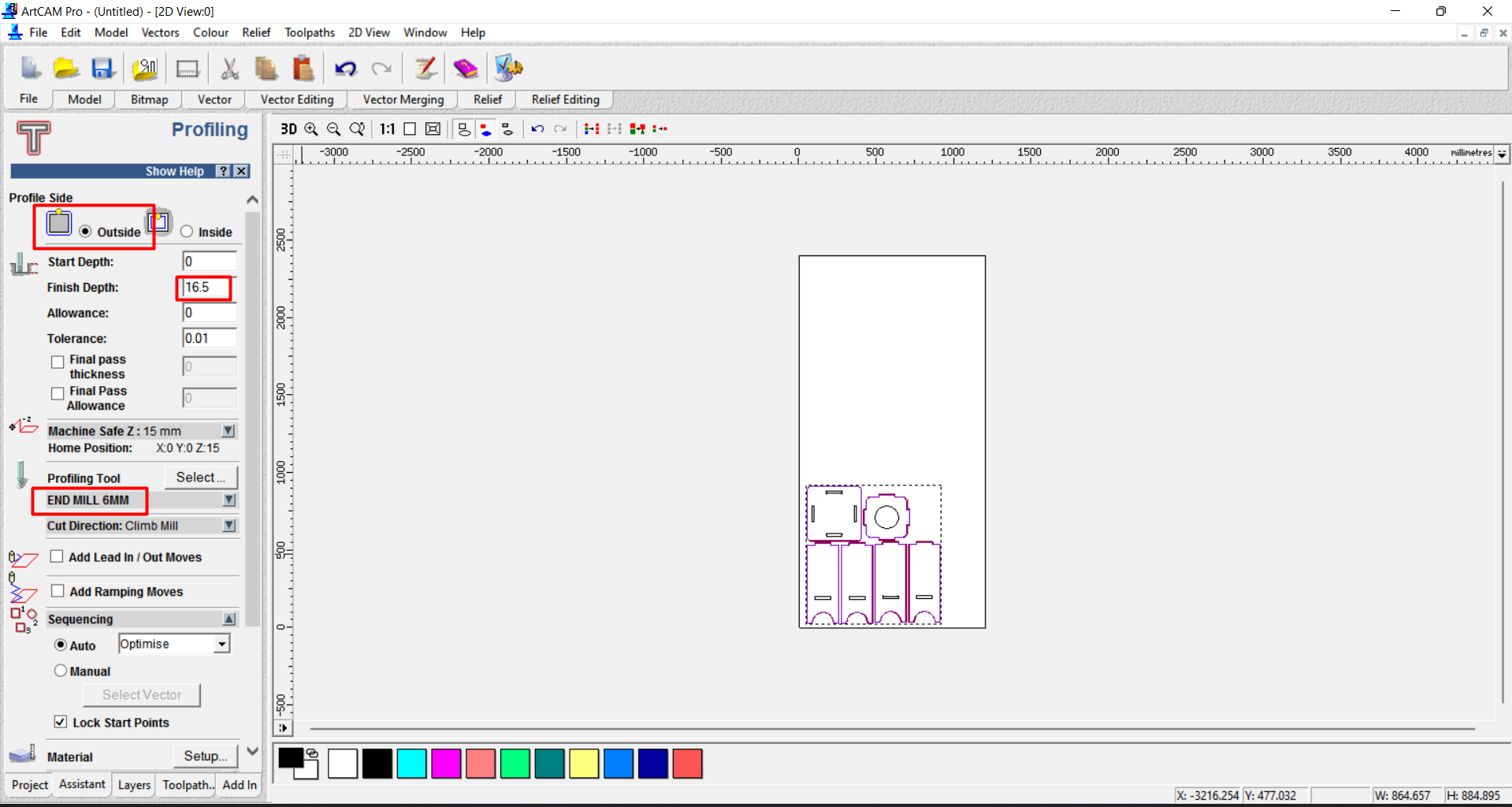
After that I select the profile side as outside frame and then select start depth 0 and material cutting thickness about 16.5mm. My material size is about 16mm. I am taking 0.5mm extra for better cut.
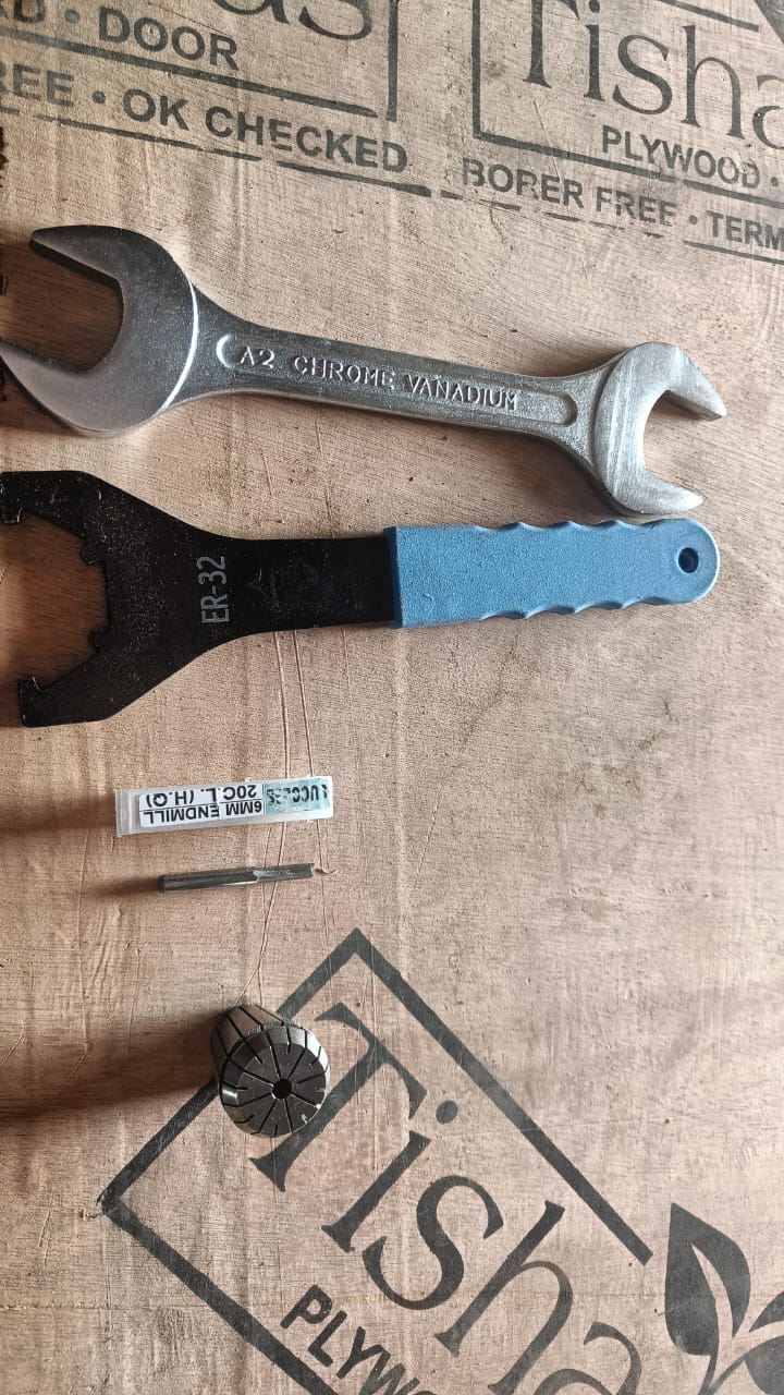
Then I select the 6MM end mill tool for cutting.
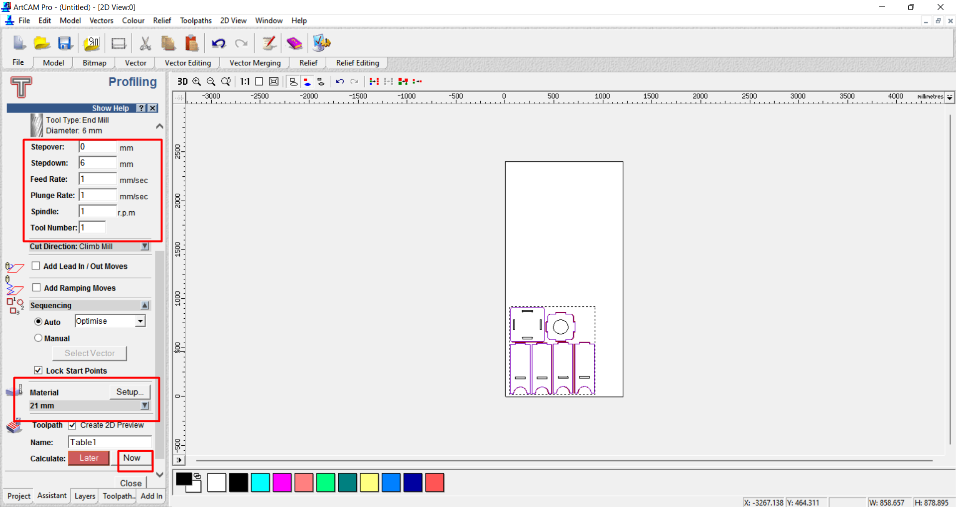
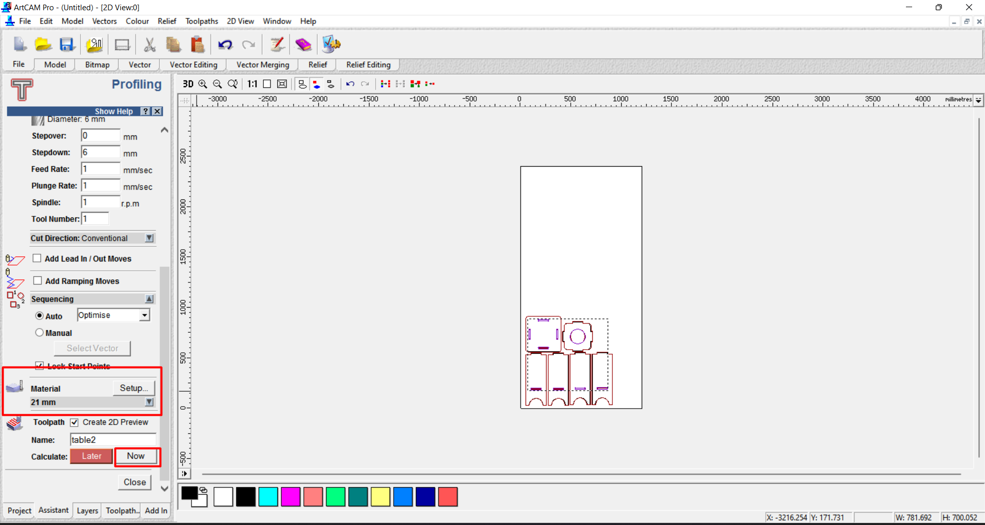
After selection of Cutting tool I set the parameter for my tool. I set stepover zero for the cutting process. I set the stepdown as 6mm. Means my tool cut the 6mm material in one pass. Then I select the material size as 21 mm. I dont know why at this point we have to take 5mm extra material size. and then I save this tool path.
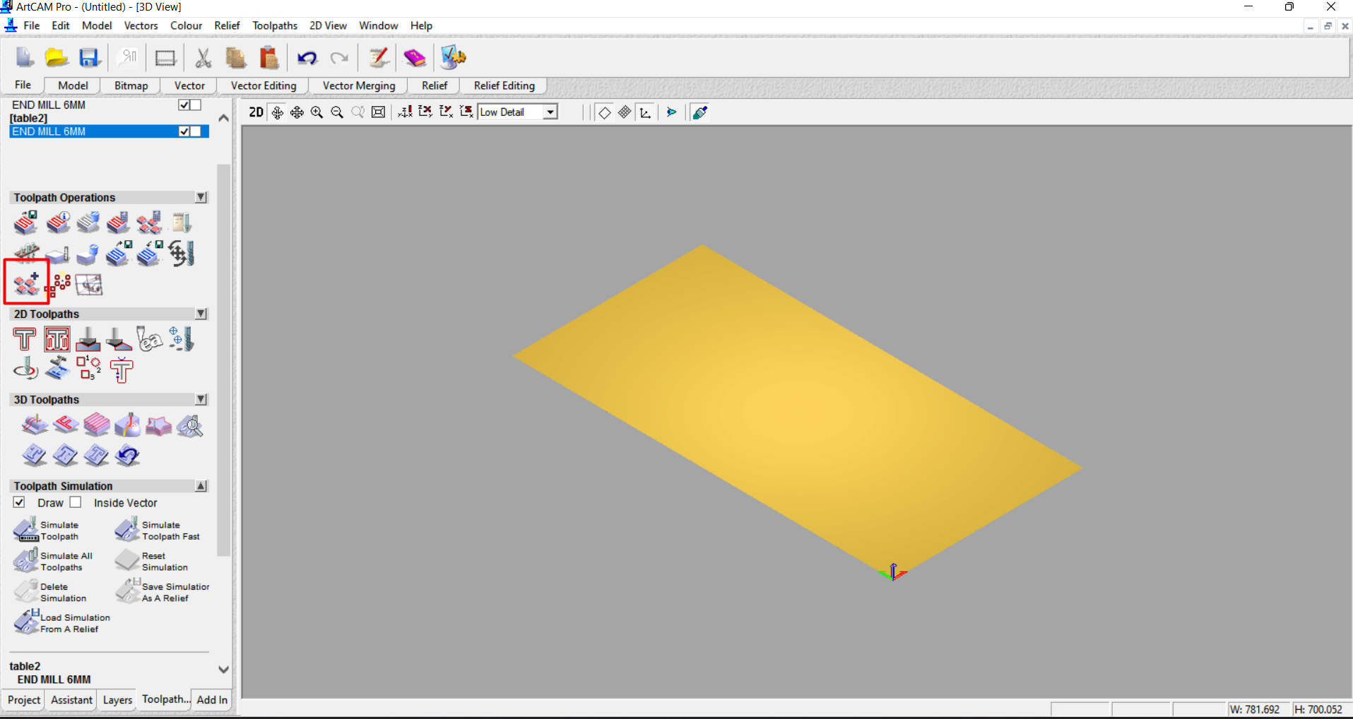
After that I create the toolpath for inside profiling.
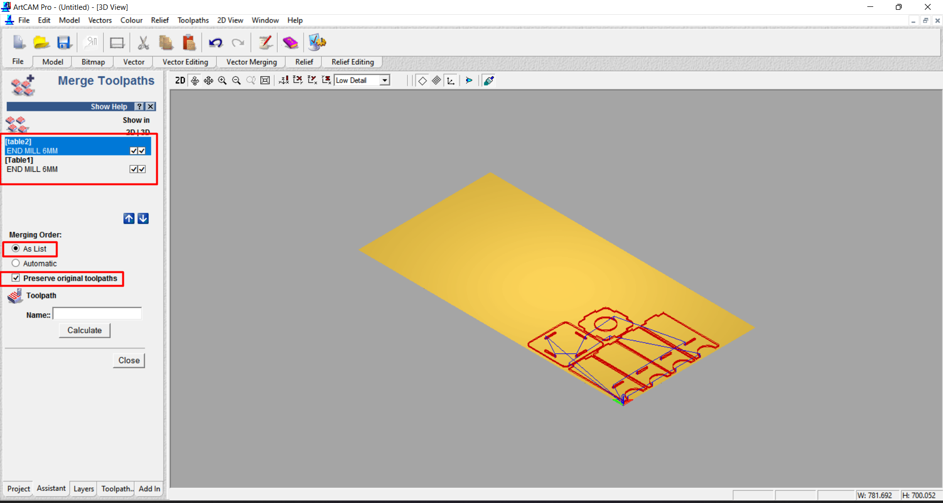
Now I am using same tool for inside and ouside cutting and I created different toolpath for them . Now I am not changing the tool so I have to merge this toolpath.
So I select the merge toolpath option and then select the sequence of cut. Firstly I cut the inside frame and then I cut outside frame.
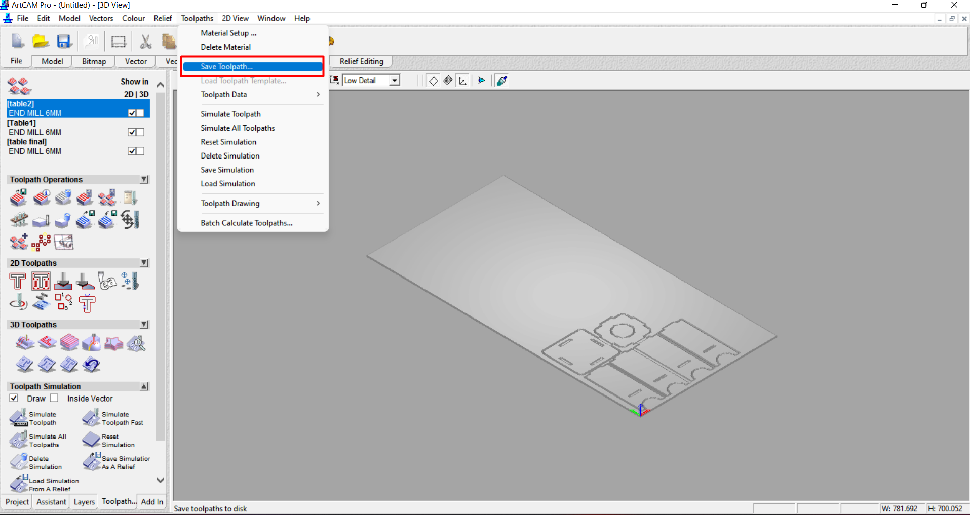
Then I ckeck the toolpath simulation.
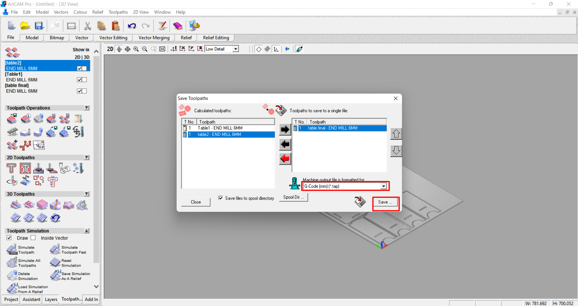
After that I save the toolpath in drive.
Machining process
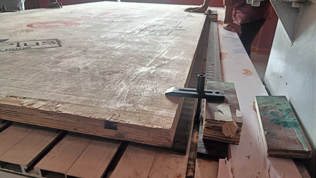
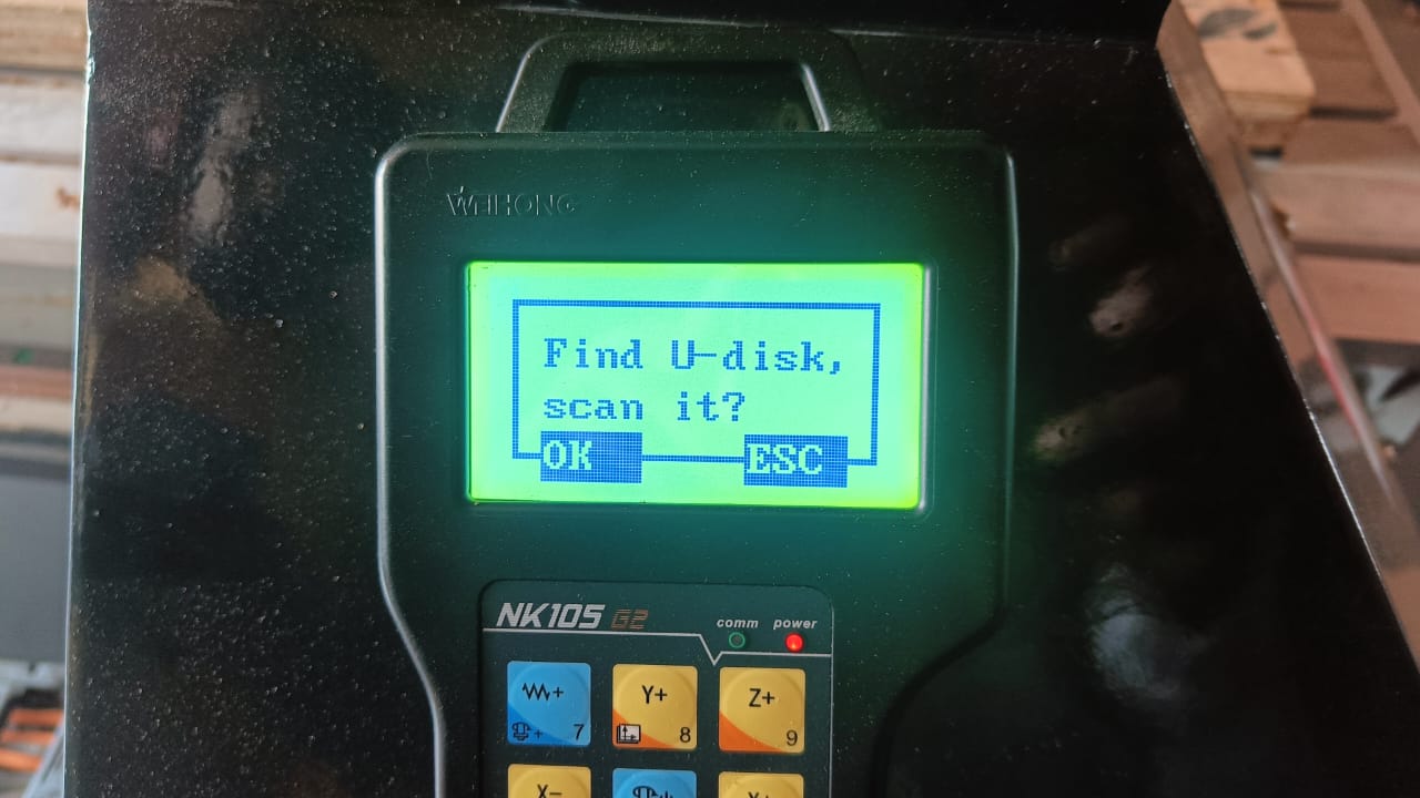
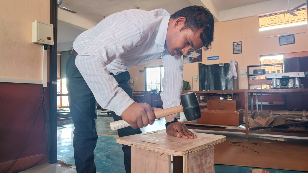
Then I insert the pendrive in machine. This machine have remote to control all the things. Firstly I set the material and tight them by pins.
After this I set the tool in the machine.
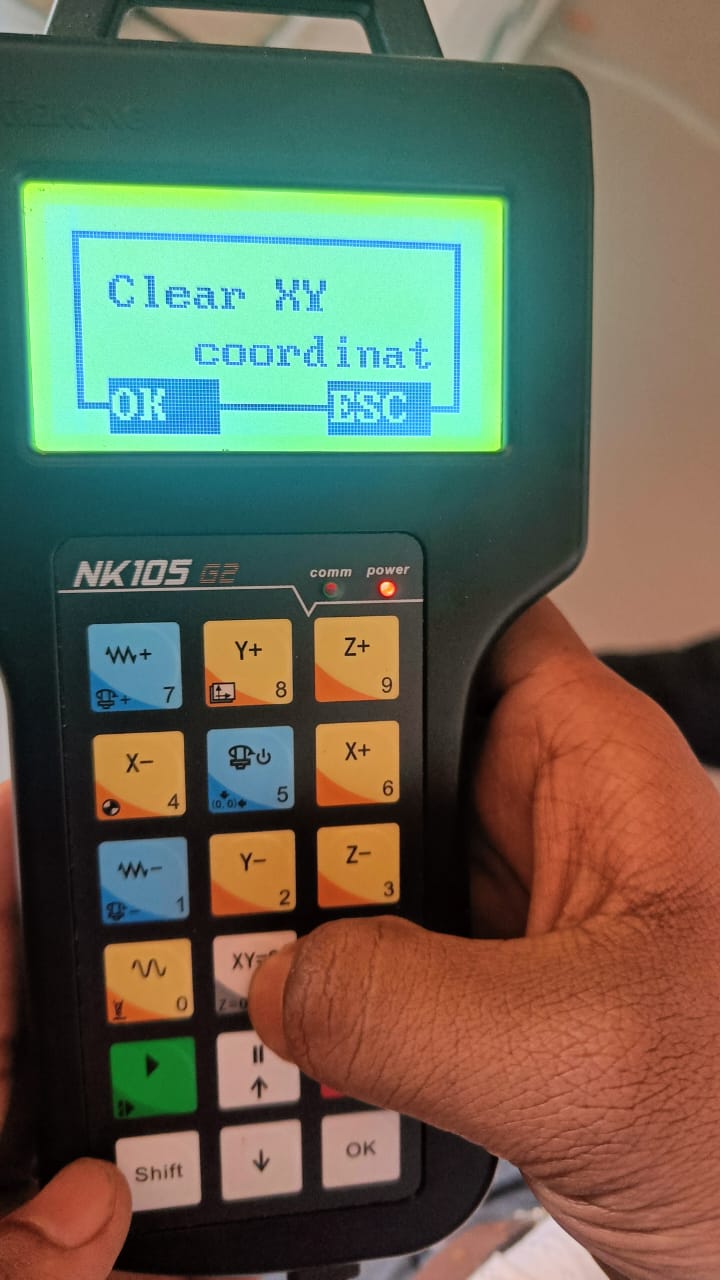
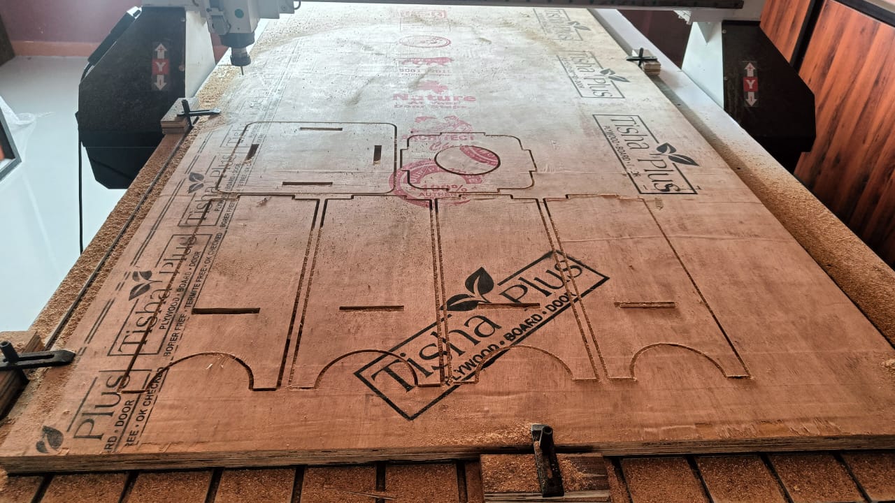
After That I set the origin of machine and then copy the file in the machine memory. Then I load the file and start cutting.